Fluid levels
After creating the compartments and incorporating the well data by assigning the logs (i.e. fluid logs, net rock logs, pressure logs), you move on to the Fluid Levels form (model > Fluids).
The table displays information based on the aggregated well data per compartment. Each compartment will be confronted with its own aggregated well data. Since the workflow assumes hydrostatic equilibrium within a compartment, any inconsistency or violation to this equilibrium will be indicated as a warning. For example, if oil is seen below water in fluid logs within the same compartment, a warning will show up as "Deepest Well ODT is deeper than or equal to Shallowest Well WUT". Based on these warnings you can decide to revisit the fluid boundaries.
Note that if different wells in a compartment have seen a FWL, then you can expect the values to differ to some degree because of varying capillary entry pressure. You can set the fluid levels for each compartment in agreement with the well data. You can QC the fluid levels in the Well View and 3D View. If needed, you can make adjustments to the fluid levels on the Fluid Levels form, and in the Well View. See Visualizing and editing fluid level surfaces for more information. The compartment FWL should be close to the FWL seen in the wells, if any, but it does not necessarily need to be exactly the same.
When the hydrocarbon reservoirs indicate presence of oil below the FWL, it should be modeled with a Paleo FWL. For example, if a reservoir was in a drainage equilibrium after the oil migration, then a structural tilting can cause the part of the hydrocarbon volume initially above FWL to move below the FWL. The Paleo FWL movement could also be amplified by cap rock leakage allowing water encroachment from aquifer.
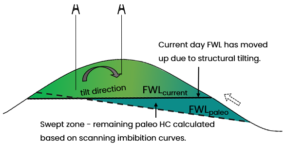
An example schematic demonstrating formation of paleo zone in the reservoir. Paleo fluid level surfaces are stored in the Fluid Compartments folder of the Fluid Model. click to enlarge
In JewelSuite Subsurface Modeling, you can model the free water levels in the reservoir with paleo zones. The Paleo FWL can be set at a fixed depth or a surface can be provided as input for a tilted Paleo FWL. You can model the saturation values in paleo zones on the Saturation Functions form.
- Read-only cells Displayed with gray font color. You cannot modify the information.
- Editable cells You can either enter manually or use the autofill button.
- Manual entries Displayed with black font color.
- Autofilled information Displayed with black font color and italic.
Checkboxes at the top of the form (above the table)
- Show Well Data Check the adjacent checkbox to show the Well Gas Data and Well Oil Data columns that consists of fluid log information.
- Show Paleo Free Water Level Check the adjacent checkbox to show the Paleo FWL columns.
- Enable fluid model as simulation input Check the checkbox to activate the Simulation Input columns, and make the fluid model selectable on the Assign Data form for your simulation concept.
Table columns
- Name Name of the fluid compartment, read-only.
- Zone Name of the zone, read-only.
- Fluid Leg Indicates the type of fluid(s) present in the compartment, editable. You can either modify it using the drop-down list, or you can use the Autofill Fluid Levels button if the fluid log information is available. GOC and/or FWL cells will become active automatically based on the Fluid Leg selection.
- TOP (Compartment Top) The shallowest depth of a compartment.
- Well Gas Data Only populated if gas is present in the assigned fluid logs, read only.
- GUT (Gas-Up-To) The shallowest GUT seen in wells intersecting the compartment.
- GDT (Gas-Down-To) The deepest GDT seen in wells intersecting the compartment.
- GOC (Gas Oil Contact) GOC of the corresponding compartment. Active only when the 'Fluid Leg' is specified as 'Gas and Oil'. You can either enter a value manually, or you can use the Autofill Fluid Levels button if the fluid log information is available.
- Well Oil Data Only populated if oil is present in the assigned fluid logs, read only.
- AGOC (Average Gas Oil Contact) The average GOC seen in wells intersecting the compartment. Only populated when the 'Fluid Leg' is specified as 'Gas and Oil'.
- OUT (Oil-Up-To) The shallowest OUT seen in wells intersecting the compartment.
- ODT (Oil-Down-To) The deepest ODT seen in wells intersecting the compartment.
- Free Water Level (FWL) FWL of the corresponding compartment. Active only when the 'Fluid Leg' is specified as 'Gas' or 'Oil' or 'Gas and Oil'. You can either enter a value manually, or you can use the Autofill Fluid Levels button at the base of the form if the fluid log information is available.
- Tilted FWL Check the box in the Tilted column next to FWL to assign a Tilted FWL Surface to a fluid compartment. You can choose the tilted surface from the drop-down list in the Tilted FWL Surface column. To be available for selection, the tilted surface should be of type 'Fluid contact', stored under Data > Fluid Contacts and should have a tri-mesh or 2D grid representation. The tilted fluid contact surface is sampled at the cell center location for each grid cell. See Creating a tilted fluid level surface for more info. You can create a surface using the Function-based Property Modeling workflow and assign the surface as tilted FWL; this allows you to insert uncertainty in volumetric studies while defining the function property model.
- Clipping Priority Select an option for the clipping priority of fluid level surfaces from the drop-down menu. This column is active only if you have selected 'Gas and Oil' in the Fluid Legs column, assigned along with a tilted FWL surface. If a compartment also contains a paleo FWL, the clipping priority has precedence, clipping the paleo FWL to the current FWL and/or GOC.
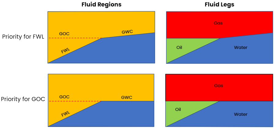
Schematic showing the behavior of the clipping priority for tilted FWL and GOC, and the resulting fluid region and fluid leg properties. click to enlarge
- Paleo Free Water Level (Columns only enabled when the 'Show paleo free water level' checkbox at the top of the table is checked) Enter a value for the Paleo FWL of the corresponding compartment. Active when the Show Paleo Free Water Level option is checked, and when the 'Fluid Leg' is specified as 'Gas' or 'Oil' or 'Gas and Oil'.
- Tilted FWL Check the box in the Tilted column next to FWL to assign a paleo Tilted FWL Surface to a fluid compartment. You can choose the tilted surface from the drop-down list in the Tilted FWL Surface column. To be available for selection, the tilted surface should be of type 'Fluid contact', stored under Data > Fluid Contacts and should have a tri-mesh or 2D grid representation. See Creating a tilted fluid level surface for more info. You can create a surface using the Function-based Property Modeling workflow and assign the surface as tilted FWL; this allows you to insert uncertainty in volumetric studies while defining the function property model.
Uncertainty This parameter can be propagated as a parametric uncertainty in a probabilistic volumetric calculation with the study strip. Click the uncertainty symbol next to the FWL entry field to open the Uncertainty Parameter dialog. If your fluid compartment consists of oil and gas, you can also model the FWL uncertainty while defining the GOC uncertainty on the Fluid Levels Uncertainty dialog. If the fluid log information is available on the Fluid Levels form, you can choose to use the
  button. For more info, see How to use the 'Autofill' button (fluid level uncertainty only). To understand the controls on the dialog, see The Uncertainty Parameter dialog. For information about parametric uncertainties and how to use them in JewelSuite Subsurface Modeling, see Incorporating uncertainty in static or dynamic modeling.
Important While modifying the fluid levels for an existing fluid model from a paleo FWL to a non-paleo FWL, or vice-verse, please make sure to map your Fluid Model Grid Properties after making changes on the Fluid Levels form.
button. For more info, see How to use the 'Autofill' button (fluid level uncertainty only). To understand the controls on the dialog, see The Uncertainty Parameter dialog. For information about parametric uncertainties and how to use them in JewelSuite Subsurface Modeling, see Incorporating uncertainty in static or dynamic modeling.
Important While modifying the fluid levels for an existing fluid model from a paleo FWL to a non-paleo FWL, or vice-verse, please make sure to map your Fluid Model Grid Properties after making changes on the Fluid Levels form. - Well Water Data Only populated if water is present in the assigned fluid logs, read only.
- AGWC (Average Gas Water Contact) The average GWC seen in wells intersecting the compartment. Only populated when gas and water are present in the assigned fluid logs.
- AOWC (Average Oil Water Contact) The average OWC seen in wells intersecting the compartment. Only populated when oil and water are present in the assigned fluid logs.
- WUT (Water-Up-To) The shallowest WUT seen in wells intersecting the compartment.
- BASE (Compartment Base) The deepest depth of a compartment.
- Assigned Wellbores The wellbores that have been selected for use on the Assign Logs form and intersect the compartment.
- Simulation Input (To enable these columns, check the 'Enable fluid model as simulation input' checkbox at the top of the table) The information entered in the Fluid Model can now be used as input to IMEX/GEM/STARS simulation cases. This reduces the amount of duplicate work and creates a stronger integration between the static and the dynamic modeling workflows. You can assign a Fluid Model to a simulation case (IMEX, GEM, STARS) via the Simulation Concept. A Simulation Concept can be defined as source to a simulation case.
- Active Check the checkbox of each compartment for which you want to carry fluid level information forward to your simulation case.
- Initialization Region ID Once you set a compartment to 'active', an initialization region ID is automatically generated.
next to the GOC entry field to open the Fluid Levels Uncertainty dialog. On this dialog, you can chose a GOC uncertainty method from four different methods that is used to define the GOC uncertainty.
next to the FWL entry field to open the Uncertainty Parameter dialog. If your fluid compartment contains oil and gas, the dialog has the option to also model FWL as an uncertainty parameter, see Fluid Levels Uncertainty dialog. If the fluid log information is available on the Fluid Levels form, you can choose to use the button. For more info, see How to use the 'Autofill' button (fluid level uncertainty only). To understand the controls on the dialog, see The Uncertainty Parameter dialog. For information about parametric uncertainties and how to use them in JewelSuite Subsurface Modeling, see Incorporating uncertainty in static or dynamic modeling.
You can specify the following information in a Fluid Model and use it as input for simulation: active compartments, initialization region IDs, PVT region IDs, depth of fluid levels (i.e., GOC, FWL), reference pressure, reference depth.
To set the fluid levels per compartment
- Select the fluid model of interest. To check the associated structural model and the assigned fluid log set, hover over the factsheet icon (
 ) adjacent to the fluid model drop-down box.
 - The Fluid Leg and corresponding GOC and/or FWL (optionally in combination with a tilted FWL and/or uncertainty) can be edited; the rest of the table is read-only and for information purposes only.
- If you have assigned a fluid log set on the Assign Logs form, you can choose to autofill the table based on this log data. To do this, click on the Autofill Fluid Levels button (
 ) at the bottom left corner of the form. See How the 'Autofill Fluid Levels' button works for more info.
 - Click OK to set the fluid level data per compartment and move to the next form in the workflow or click Apply to set the data and keep the form open.
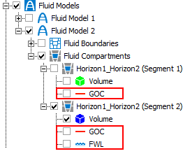
Fluid level surfaces are stored in the Jewel Explorer. click to enlarge
Once the fluid level data has been set, fluid level surfaces are generated and stored in the JewelExplorer in their corresponding fluid compartment folder (Fluid Models > Your Fluid Model > Fluid Compartments > Your Compartment). See Visualizing and editing fluid level surfaces for more information.